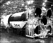
![S-IC stage SATURN V launch vehicle. [link to a larger picture]](p197s.jpg)
[191] The lower stages for the Saturn I and Saturn IB, designed and built for Earth-orbital operations, traced their ancestry back to the Juno V. Saturn I and IB technology was characterized by the "bargain basement" approach-off-the-shelf tankage, and available engines. Saturn V, a vehicle designed for lunar voyages, required new engineering concepts. Designers for the S-IC and S-II stages tried to follow NASA's general guidelines to use proven technology in the big new boosters, avoiding problems and delays. Nonetheless, problems abounded.
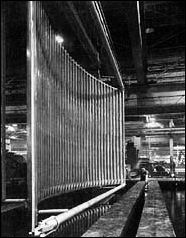
In the first place, there was the problem of proportions. The S-IC and S-II both were sized to a 10-meter diameter. In the fabrication of booster tankage, new tooling of unique size and capabilities had to be built, and fabrication of the tank cylinders and domes required circumferential welds and meridian welds of unprecedented length. For manned flights, the welds also had to pass stringent inspection to "man-rate" the Saturn V vehicle. The difficulties faced by welding engineers and technicians were formidable. In terms of the nearly perfect welds required for the man-rated stages, weld passes of several dozen centimeters were considered possible (though highly difficult) within the state of the art; now, requirements for the S-IC and S-II demanded nearly perfect welds of several dozen meters. The task became a maddening cycle of "cut-and-try" operations. The long welding runs generated unmanageable distortions in large-circumference cylinders. Additional difficulties included coping with the varying thickness of pieces being joined by the welding pass; quality requirements for the integrity of welded seams and alignments of the components created still more revisions to operational manuals. Experienced welders had to be taught the new techniques through on-the-job instructional classes conducted on-site by the contractor.
[192] The problem of size confronted both major contractors for the Saturn V lower booster stages, Boeing being contracted for the S-IC, and North American* for the S-II. Although the S-II contract preceded that of the S-IC, the Boeing effort got off to a faster start largely because of the unusual role played by the Marshall Space Flight Center in the early stages of design and fabrication, and the availability of existing facilities at MSFC's Huntsville complex and at Michoud. The S-II encountered more than its share of problems, for a variety of reasons. Use of LH2 propellants in a stage of this size was unique. There were insulation problems, materials and fabrication problems, and, in the opinion of MSFC, management problems. The difficulties were overcome, but not without casualties.
When the contract to build the biggest stage of the Saturn V, the S-IC first stage, was awarded to Boeing on 15 December 1961, general outlines of the first-stage booster were already fairly well delineated. The main configuration of the S-IC had already been established by MSFC, including the decision to use RP-1, as opposed to the LH2 fuel used in the upper stages. Although LH2 promised greater power, some quick figuring indicated that it would not work for the first stage booster.
Liquid hydrogen was only one half as dense as kerosene. This density ratio indicated that, for the necessary propellant, an LH2 tank design would require a far larger tank volume than required for RP-1. The size would create unacceptable penalties in tank weight and aerodynamic design. So, RP-1 became the fuel. In addition, because both the fuel and oxidant were relatively dense, engineers chose a separate, rather than integral, container configuration with a common bulkhead. The leading issue prior to the contract awards related to the number of engines the first stage would mount.1
The C-5 configuration, late in 1960, was generally portrayed as a rocket with four F-1 engines in the first stage. Not everyone was happy with this approach, particularly Milton Rosen at NASA, recently tagged by Brainerd Holmes as the new Director of Launch Vehicles and Propulsion in the Office of Manned Space Flight. At the direction of Holmes, Rosen organized a special committee to hammer out conclusions and configurations on launch vehicles (see chapter 3). The group moved into a block of motel rooms in Huntsville for an intensive two-week stint, including, as Rosen recalled, one marathon stretch of five days of almost [193] around-the-clock negotiating. Among other things, the committee's report, delivered to Holmes on 20 March 1961, recommended five, not four, engines in the first stage.
Rosen apparently took the lead in pressing for the fifth engine, consistent with his obstinate push for a "big rocket." The MSFC contingent during the meetings included William Mrazek, Hans Maus, and James Bramlet. Rosen argued long and hard with Mrazek, until Mrazek bought the idea, carried the argument to his colleagues, and together they ultimately swayed von Braun. Adding the extra power plant really did not call for extensive design changes; this was Rosen's most convincing argument. Marshall engineers had drawn up the first stage to mount the original four engines at the ends of two heavy crossbeams at the base of the rocket. The innate conservatism of the von Braun design team was fortunate here, because the crossbeams were much heavier than required. Their inherent strength meant no real problems in mounting the fifth powerplant at the junction of the crossbeams, and the Saturn thus gained the added thrust to handle the increasingly heavy payloads of the later Apollo missions. "Conservative design," Rosen declared, "saved Apollo."2
At second glance, MSFC people themselves found no good reason not to add the extra engine, especially with the payload creeping upward all the time. "I had an awfully uneasy feeling, you know," von Braun remembered; "every time we talked to the Houston people, the damn LEM [lunar excursion module] had gotten heavier again." The added F-1 also relieved some of the concern about accumulating exhaust gases, with explosive potential, in the large space between the original four engines, and helped solve a base-heating problem in much the same way. The physical presence and exhaust plume of engine number five filled the void and directed gases and heat away from the base of the first stage. At a Management Council Meeting on 21 December 1961, NASA formalized the five-engine configuration for the S-IC.3
In the past the Army Ballistic Missile Agency (ABMA) had performed its own preliminary design work-and even fabrication-on the first stage of launch vehicles. At Marshall the designers approached the S-IC somewhat differently. They enlisted Boeing's cooperation at a much earlier stage of the game, giving increased responsibility to the contractor. After signing the contract in December 1961, Boeing engineers worked "elbow-to-elbow" with MSFC in finalizing details of the big first stage. It was a mutually beneficial environment. With so many other irons in the fire, Marshall did not have the manpower to lavish on the S-IC, and Boeing got the chance to influence the outlines of the booster it would be building later. By the summer of 1962, Boeing had almost 500 engineers and technicians working on site at MSFC, and another 600 installed in a sprawling, hastily reconditioned cotton mill in downtown Huntsville known as the "HIC Building" (for Huntsville Industrial [194] Center). Boeing's Huntsville operations concentrated on final hardware design and continuing liaison with MSFC.
Boeing also had about 450 people at Michoud, preparing for manufacturing operations. Michoud was also the management focal point for the S-IC, with the Saturn Booster Branch, under George H. Stoner, located there. From Michoud, Stoner presided over several far-flung elements. In Seattle, the company's home office, Boeing personnel carried out engineering and research support for Saturn, such as wind tunnel studies and other specialized engineering data. At Boeing's Wichita plant, the heavy tooling for Michoud was prepared, and subassemblies used in making up the tankage and other components of the booster were fabricated.
Michoud itself operated under Richard H. Nelson, with four sections for operations, quality and reliability assurance, engineering, and booster test. Engineering and manufacturing procedures were also laid out and coordinated with MSFC, covering a multitude of items, ranging from accidents, to test procedures, to the controlled use of precious metals, to "unplanned event reports." MSFC received many volumes of company reports, formal and informal, regarding the progress and problems of both the S-IC stage and the Michoud operations. Annual progress reports to the Marshall center summed up company activities. Topics included road construction; lighting in conference rooms; electrical troubles in the S-IC lifting derricks; and changes in stage design, test stands, and production. The company also reported on its special training programs for new employees in some of the esoteric arts of welding large space vehicles, radiographic inspection, and several varied courses in a number of specialized skills for production of booster rockets.4
This unusually intertwined work between government and contractor prompted Stoner at one point to ask von Braun, somewhat plaintively, why pick on Boeing? Why not allow the company to forge ahead on its own, like Douglas and North American? MSFC stemmed from the Redstone Arsenal, and MSFC managers intended to maintain an in-house capability. As von Braun once explained, contractors might present beautifully turned out pieces of sample hardware, expounding the virtues of exotic lightweight alloys and advanced welding technology. MSFC remained skeptical. Highly finished work on small samples was one thing. What about welding very large, oversized segments together where alignment and integrity of weld were very tricky to achieve? MSFC wanted to maintain its expertise, to make sure that alloys and welds would really work before the manufacturer began production. In this respect, Matt Urlaub, MSFC's manager for the S-I stage, suggested additional reasons for staying close to Boeing. All of Marshall's stage contracts went to companies accustomed to working under Air Force jurisdiction, a situation that gave the companies considerable latitude in [195] technical design, fabrication and manufacturing procedures, and day-to-day operations. These companies were also principally airframe manufacturers. Marshall felt, however, that it had great competence in R&D, building prototypes, and technical management in rocketry. Therefore, Marshall should exert considerable influence in its areas of expertise early in the game, then let the contractors handle the production aspects. Douglas (with the S-IV/IVB contract) and North American (the S-II contract) were to manufacture their respective stages on the West Coast, but Boeing was to manufacture the S-IC stage at Michoud-in Marshall's backyard, so to speak. So Boeing got an unusually close overview, and MSFC also got experience in how to handle its other contractors with Air Force experience.
Stoner later admitted that the close alliance with MSFC at the start had been extremely fruitful, working out problems before they arose, avoiding approaches that might have resulted in dead ends, and capitalizing on MSFC's engineering style and experience-especially welding technology-to avoid production difficulties and cost overruns. From his vantage point at NASA Headquarters, Milton Rosen accurately gauged the impact of MSFC on Boeing. All the expertise behind the V-2, Redstone, Jupiter, and Saturn I went into the S-IC stage, he noted. Any mistakes would have had to be Marshall's-and there were not many. "With Boeing, all the power of Marshall's engineering and experience went into that (S-IC) rocket," Rosen said.5
Consistent with the MSFC insistence on in-house experience and capability, Marshall built three ground-test stages of the S-IC and the first two flight models. With the planned S-IC production facilities at Michoud still being modified, the MSFC production not only gave Boeing and Marshall people valuable early production experience, but also offered earlier delivery dates for test and flight stages. Using the tooling built at Boeing's Wichita facility and later installed at Marshall, Huntsville produced the S-IC-T, the S-IC-S, and the S-IC-F, and the first two flight models, the S-IC-1 and -2. The "T-Bird," as it was called, was built for static test firing; the "S," as a structural test model for load tests (it had no engines); and the "F," as a facilities test stage (also with no engines) to send to Cape Kennedy to aid in the checkout of the launch complex assembly buildings and launch equipment. Manufacture of these stages started in staggered sequence during 1963. In addition, MSFC planned to make the first complete fuel tank at Huntsville; this would be the first item turned out on S-IC tooling. Based on early tests of the fuel tank, engineers intended to verify the design loads anticipated for both it and the oxidizer tank. Then production could proceed on all components.
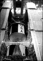
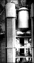
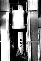
[196] As MSFC finished using the initial batch of tooling equipment, it was sent on to Michoud for Boeing's subsequent use there, so that portions of several stages were under construction at the same time. Approximately 7 to 9 months were required to fabricate and assemble the tanks, the longest lead-time items, and about 14 months for the complete assembly of an S-IC. For its first unit, Boeing built a ground test dynamics model, the S-IC-D, giving the company production team at Michoud some experience before starting on its first flyable booster. The S-IC-D was planned to carry one genuine engine and four simulated engines. After shipment to Huntsville, the plan was to join this first stage with the S-II and S-IVB for dynamic tests of the total vehicle "stack" in a test facility at MSFC. One other test unit was produced at Michoud-a full-sized dummy model of the S-IC stage, billed as the largest mockup in the world. Built of metal, wood, fiberglass, etc., the mockup was primarily used to help fix the sizes and shapes of parts, test the angles of tubes and lengths, and see where wire bundles would run.
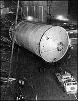
Because Chrysler produced the last Saturn I and Saturn IB first stages at Michoud, Boeing had to share the facility, but took 60 percent of the available space for the larger S-IC stage. The girth of the first stage also dictated removal of some of the overhead trusses and air conditioning ducts to allow a 12.2-meter clearance for fabrication of the stages. This left a slim 0.6-meter margin for the S-IC's 11.6-meter-diameter assembly fixture.
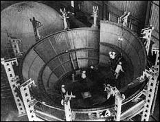
In addition, the heavy tooling required for the S-IC necessitated reinforcement of some parts of the floor. Boeing made another notable addition to the Michoud facility with the addition of a high-bay area for assembly of S-IC components. In the early stages of talks on S-IC production, the question of horizontal as opposed to vertical assembly of the tanks and components came up. The vertical assembly mode was selected, even though a new high-bay area was required, because horizontal assembly posed problems in maintaining accuracy of joints in the heavy, but thin-walled tanks. In vertical assembly, gravity held the huge parts together, although a 198-metric-ton crane was required to hoist the parts atop each other, and to lower the completed booster back to the horizontal for final finishing.6
Major components for the S-IC included the thrust structure, fuel tank, intertank, liquid oxygen tank, and forward skirt.7 As with nearly every other major segment of the towering Saturn V, these items were elephantine in their proportions.
The S-IC thrust structure absorbed the punishment of five F-1 engines at full throttle and redistributed the forces into uniform loading around the base of the rocket. The thrust structure also provided....
[198] ....support for engines and engine accessories, and miscellaneous equipment. There were also four "anchors" helping to hold the vehicle in place prior to liftoff. These aluminum forgings, some of the largest ever produced in the United States, were made in one of two presses in the country capable of 50 000 metric tons of pressure to form the basic forged billets, 4.3 meters long and 816 kilograms in weight. A tape-controlled milling machine carved out the multiple cavities, flanges, and attachment holes, leaving a finished product weighing almost one-third less. One of the distinctive features of the Saturn launch vehicle was the presence of four engine fairings and fins at the base of the S-IC and mounted on the exterior of the thrust structure. The fins added considerable stability to the vehicle, and were fabricated from titanium to withstand the 1100°C heat from the engine exhaust. The four conical engine fairings smoothed the air flow at the base of the rocket and protected the engines from aerodynamic loads. In addition, each fairing carried a pair of retrorockets to decelerate the big booster after separation from the S-II stage; the retrorockets exerted a thrust of about 400 000 newtons (90 000 pounds) during a burn time of less than a second.8
The propellant tanks included special fill and drain points to handle heavy-duty lines used to fill the big vessels at high rates; up to 7300 liters (2000 gallons) of RP-1 per minute. If left to its own devices inside the tank, the RP-1 would have settled into strata of varying temperatures, a highly undesirable situation, so the S-IC incorporated a fuel conditioning system to "stir" over 730 000 liters (200 000 gallons) of RP-1 gently by continuously bubbling gaseous nitrogen through the feed lines and the fuel tank prior to launch. To ensure proper engine start and operation, a fuel pressurization system contributed to good pressure at the fuel turbopump inlets where 10 fuel lines (two per engine) funneled RP-1 to the engines at 4900 liters (1350 gallons) per second. During the countdown, pressurization was supplied by a ground source, but during flight, a helium pressurant was supplied from elongated bottles stored, not on the fuel tank, but submerged in the liquid oxygen (LOX) tank. In this medium, the liquid helium in the bottles was in a much more compatible environment, because the cold temperature of the liquid helium containers could have frozen the RP-1 fuel. There were additional advantages to their location in the colder LOX tank. Immersed in liquid oxygen, the cryogenic effect on the aluminum bottles allowed them to be charged to higher pressures. They were also lighter, because the cryogenic environment permitted manufacture of the helium bottles with one-half the wall thickness of a noncryogenic bottle. Produced by the Martin Company, the four helium bottles, 6 meters long and 56 centimeters in diameter, were aluminum extensions of unique length. Ducts carried the cooling helium down through heat exchangers on the F-1 engines, then carried heated, expanded gaseous helium back to the top of the fuel tank for ullage pressure.9
[199] With a capacity of 1 204 000 liters (331 000 gallons), the LOX tank acquired its payload in stages, with a slow fill of 5500 liters (1500 gallons) per minute and a faster fill at a torrential rate of 36 000 liters (10 000 gallons) per minute. The special problem of the LOX tank involved the feed lines leading to the thirsty engines about 15 meters below the fuel tanks. To do the job, the S-IC used five LOX suction lines, which carried oxidizer to the engines at 7300 liters (2000 gallons) per second. To achieve such high rates of flow, the lines could not be bent around the outside of the fuel tank; therefore, designers ran them right through the heart of the fuel tank. This in turn caused considerable fabrication problems, because it meant five extra holes in both the top and bottom of the fuel tank and presented the difficulty of avoiding frozen fuel around the super-cold LOX lines. The engineering fix on this included a system of tunnels, each one enclosing a LOX line, especially designed to carry an effective blanket of insulating air. Even so, the warmer fuel surrounding lines created some thermal difficulties in keeping the LOX lines properly cool. So the S-IC used some of its ground-supplied helium to bubble up through the LOX lines, and kept the liquid mixed at a sufficiently low temperature to avoid destructive boiling and geysering, or the creation of equally destructive cavities in the LOX pumps. To pressurize the tank, the S-IC tapped a helium ground source prior to launch. In flight, the LOX tank pressurization system used a system that tapped off some of the liquid oxygen, ran it through a heat exchanger to make it gaseous (called, naturally, GOX), and routed it back into the LOX tank.
Because the immense fuel and oxidizer vessels were separate items, the S-IC required additional pieces of hardware to make an integrated booster stage: the intertank and forward skirt. The intertank structure was a full seven meters in height itself, because the large bulges of the forward fuel tank dome and aft LOX dome extended inside it. There was a considerable amount of space remaining inside the intertank structure, which was given over to instrumentation cables, electrical conduit, telemetry lines, and other miscellany. Unlike the smooth skins of the propellant tanks, the unpressurized intertank structure required other means to maintain rigidity and carry the various stresses placed on it during launch. This requirement explains the distinctive appearance of both the intertank and the forward skirt, fabricated of 7075 aluminum alloy with corrugated skin and internal stringers (versus 2219 aluminum for the tanks). Both structures also included various access doors and umbilical openings for servicing, inspection, and maintenance prior to launch. The forward skirt, three meters in height, enclosed the bulge of the LOX tank's forward bulkhead, and its upper edge constituted the separation plane between the S-IC and the S-II stages.
While Rocketdyne supplied the five F-1 engines, the hydraulic system, used to actuate the gimbals, was included as part of the S-IC design. The hydraulic system featured a somewhat unconventional but [200] convenient approach, using RP-1 fuel as the actuating fluid. Although not unique, this use was not common practice in rocket engines. RP-1 fuel admittedly displayed certain drawbacks as a hydraulic fluid: it was less viscous, more corrosive, a poor lubricant, presented contamination problems, and posed a safety hazard with its relatively low flash point. Still, the use of RP-1 was appealing because it eliminated a separate hydraulic system. The RP-1 was taken directly from the high-pressure fuel duct, routed to the gimbal system, then back to the engine fuel system. To compensate for the shortcomings of RP-1 as the fluid, special care was taken in the design of valves, and a less volatile fluid (from an external source) was used when testing indoors and during prelaunch activities.
The S-IC carried a heavy load of instrumentation, particularly in the first few flights, to record and report information on its components, temperatures, pressures, and so on, totaling about 900 separate measurements. Much of the success of this complex web of instrumentation rested on the stage's transmitters and Boeing's achievement of some significant advances in the state of the art. A company team redesigned and rebuilt a 20-watt transmitter with solid-state components, rather than vacuum tubes. Relying on integrated circuits, such units were reduced to half the size of a pea, doing the same job with higher reliability than older units the size of a baseball.
The first two flight stages of the S-IC also carried visual instrumentation that yielded some unique and striking images. A pair of TV cameras covered the fiery environment of engine start and operation. The cameras were tucked away above the heat shield-safe from the heat, acoustic shock, and vibration of the open engine area-and the lenses were connected to serpentine lengths of fiber optic bundles, focused on the engine area, and were protected by special quartz windows. Fiber optic bundles also provided a field of vision into the LOX tank, with a pair of motion picture cameras using colored film to record behavior of the liquid oxygen in flight. The system offered a means to check on wave and sloshing motions in the huge tank, as well as the waterfall effects of LOX cascading off internal tank structures during the boost phase. Another pair of color motion picture cameras captured the spectacular moment of separation from the S-II stage. Twenty-five seconds after separation, the color cameras were ejected in a watertight capsule, attached to a parachute for recovery downrange in the South Atlantic.10
Although MSFC intended to have the S-IC developed and produced within the state of the art, the S-IC's mammoth dimensions created [201] difficulties, not only in design, but in manufacturing and testing. In a speech to an annual meeting of the American Institute of Aeronautics and Astronautics in 1965, Whitney G. Smith, of Boeing's Launch Systems Branch, emphasized that "the tremendous size of this vehicle, coupled with its design complexities, have created many unique and challenging problems for the aerospace materials engineer." The basic complex challenge of the S-IC involved the scale of the stage itself in that it not only stretched the largest available tools to their maximum capacity, but also required the development of new techniques and facilities. Even old hands in the aerospace industry became fascinated by the size and scope of the S-IC stage fabrication and assembly, and magazines like Aviation Week and Space Technology featured blow-by-blow accounts of fabrication and welding procedures with technical asides on each step of the process.
The arm-in-arm approach of Boeing and MSFC in the early S-IC design studies continued into the development of jumbo-sized tooling and fabrication concepts for the stage. Under the watchful eye of Jack Trott, MSFC's deputy director of the Manufacturing Engineering Division at that time, tooling such as assembly jigs and weld fixtures were tested; once they were deemed workable, Boeing received approval to build duplicates for installation later at Michoud. This phase of tooling-up required a certain amount of flexibility in the tool manufacturing scheme, because each Apollo mission featured variations and required a slightly different S-IC for each launch. For this reason, the tooling had to have a high degree of changeability. Boeing also worked with smaller inventories (because of probable design changes), and planned built-in time allowance in the manufacturing scheme to accommodate changes to a vehicle already moving along the production line.11
Some techniques did not work out, as in the case of chemical sculpturing of the outsized gore segments used for the curved bulkheads of the fuel and oxidizer tanks. Each bulkhead was made up to eight of the large gores, shaped like a wedge of pie, which had been made from a base segment and apex segment. The curved gores were manufactured with a precise tapering thickness toward the tip, and included a waffled pattern in the base segment. Because of the contoured shape and various raised surfaces, a chemical milling process seemed most attractive for sculpturing the curved pieces. But by 1965, trial-and-error development led Boeing to rely on machine milling of the gore segments in the flat, and then hydraulically bulge-formed to the correct contours.12 The enormous bulge-formed dies to do this kind of job were located at Boeing-Wichita, where 90 percent of the parts for the S-IC were fabricated, then shipped to MSFC and Michoud to be manufactured into a complete booster stage.
In addition to bulge-forming gore segments from heavy aluminum sheets (up to 27.6 square meters in size), Boeing-Wichita devised a technique that simultaneously age-hardened and formed the large aluminum alloy plates in an electric furnace. The plates that made up the tank [202] walls weighed five metric tons each, before they were milled down to weigh only one ton with walls about 60 millimeters thick. The tape- controlled form milling exposed the integral stiffeners, configured so that they were parallel to each other when the tank was in the curved condition. Mathias Siebel, director of MSFC's Manufacturing Engineering Laboratory, remarked that many test panels had to be machined to get the spacing and machine control tapes set up just right. Normally, the fabrication technique involved taking the 3.4 x 8-meter plates and rolling them to shape, heat treating in a restraining fixture, then further processing to eliminate distortions. Using its electric furnace, the Wichita plant turned out integrally stiffened fuel and LOX tank walls by clamping the piece to a precisely curved fixture that was a built-in part of the furnace. In this way, tank walls were age-hardened by heat and formed in the same process.13
Eventually, the dozens of pieces of metal to make the S-IC tanks arrived at MSFC or Michoud to be welded together. The outsized dimensions of the pieces dictated modifications to standard welding procedures in which the welding tool was stationary and the piece to be welded was turned. Instead, the welding tools in most cases traveled along tracks over the components, held rigidly in huge jigs. The big problem was distortion, always a plague in the fabrication of light vessels (such as the Saturn tanks), and the S-IC propellant tanks were among the largest such lightweight vessels ever built. The primary cause of distortion was heat, and heat was unavoidable on the extended welding passes needed to make the vessel. Several actions were undertaken to reduce the heat and distortion factors. To ensure maximum weld conditions, the work was conducted in special areas with temperatures below 25°C and the humidity below 50 percent. Otherwise, too many weld defects occurred in the work. In addition, special techniques were employed at the welding surface, particularly the use of the tungsten-inert-gas (TIG) process. The TIG method had been used in other applications but never to such a great extent as in the fabrication of aluminum tanks for Saturn. The inert gas shield protected the weld from air, offered more control of the process, and allowed anywhere from 2 to 30 passes over a single weld joint. An S-IC had about 10 kilometers of welding with every centimeter inspected. Under these constraints, welding teams numbered between 10 and 15 specialists, with procedures lasting up to eight hours and sequenced like the countdown of a launch vehicle.14
Major welding operations entailed the joining of base and apex segments of the bulkhead gore segments into complete domes for the fuel and LOX tanks. The domes presented some difficult welding challenges when it came to welding various fittings and the several duct lines, because high residual stress in the huge curved components occasionally created a distortion effect known as "oil-canning." The distortions produced uneven surfaces that in turn upset the close [203] tolerances required for other welding operations. The LOX duct lines, for example, were welded to fittings in the curved bulkhead. Specifications allowed no more than 0.5 millimeter mismatch between the duct and the bulkhead fitting, involving a bias-cut joint 63 centimeters in diameter. Rather than return to a time-consuming process of age-forming in a special fixture, MSFC developed a special "electromagnetic hammer" to iron out the distortions. High voltage passing through a large coil created opposing fields between the distorted part and the "hammer." The opposing fields repelled, and because the mass of the coil was greater than the mass of the part, the part actually moved to eliminate the distortion. There was no physical impact between the part and the coil. In fact, demonstrators liked to lay a sheet of tissue paper between the coil and part, proceed with the "hammering," and remove the tissue undamaged.
After several materials were rejected, the aluminum used in the fuel and LOX tanks was a 2219 alloy, chosen because of its variations in size, required for the S-IC, its weldability, and its resistance to stress corrosion. The propellant tank walls were welded into king-size hoops (10-meter-diameter), two for the fuel tank cylinder and four for the LOX tank cylinder. The tank cylinders included numerous circular slosh baffles designed for structural circularity and for slosh control. Additional slosh control was created by the installation of cruciform slosh control baffles in the aft domes of the fuel and LOX tanks.15
Before the components of the propellant tanks were welded, they were subjected to special cleaning processes, with most attention given to the LOX tank. For all its desirability as an oxidant, LOX is highly volatile under certain conditions presenting unusual problems in the handling and fabrication of parts in contact with the oxidizer. Mixed with a hydrocarbon like grease or oil, LOX becomes extremely unstable, and even a very small spark can ignite the capricious stuff. Theoretically, if a worker left a fingerprint on the inside of a LOX tank, the oil in the fingerprint could cause an explosive situation. So, all surfaces coming in contact with LOX were kept virtually spotless with a rating of "LOX clean". At Michoud, Boeing prepared a series of big vats for cleaning components such as valves, tubes, and tank wall segments.
Depending on the specifications, several different cleansing processes could be used and technicians wore special lint-free gloves. A typical operation began by spraying the part with a degreasing compound, followed by washing in a detergent solution. Rinsing required water that had been carefully de-ionized and decontaminated. The part was then deoxydized with a solution of nitric acid and rinsed once more-but only in preparation for additional cleaning. After being heated, the part underwent the next step; an etching process that actually removed a micro-thin layer of surface material. Following a final rinse, drying was done with a blast of hot air, which was especially filtered to be oil-free. In addition to the cleaning of the segments, subassemblies like bulkheads.....
 |
|
 | |
|
. |
|
|
|
 |
. |
 | |
|
. |
|
|
|
|
|
|
 | |
[206] ....also received the cleaning treatment in Boeing's "major component cleaning facility," jocularly known at Michoud as "the world's largest dishwasher." The dishwasher, a box 12 meters square and 6.7 meters high, was lined with stainless steel. A complete tank bulkhead was rolled in and washed down with special chemicals dispensed from revolving pipes outside and inside the dome. The evolving pipes and spraying action made the nickname inevitable.16
When it came to joining the tank wall cylinders and domes together, the size of the S-IC required the production of a special rig known as the Y-ring. The longest "lead-time" item in the S-IC manufacturing process, the Y-ring required two months to complete at Michoud. It consisted of three aluminum billets welded into a ring and then carefully machined to the correct shape in several closely controlled phases.17 The Y-ring was designed to eliminate lap joints where the tank domes, walls, and adjoining structure (like the interbank segment) came together. Each Y-ring featured one straight side as the meeting point for the vertical sides of the tank well and adjoining structure, and one appropriately angled area to serve as the meeting point for the upper or lower tank dome.
In the vertical assembly area at Michoud, complete fuel and LOX tanks were formed and then hydrostatically tested to 105 percent of the total pressure anticipated in a mission. This overpressurization created a certain amount of danger in the test area, so the test was monitored by a bank of closed circuit TV cameras. Demineralized water was used in the test sequence, with special dyes added to show up on the cameras if minute seepages occurred. The hydrostatic tests exerted so much force on the tanks that their dimensions were actually stretched by 1.3 centimeters at the bottom. After flushing and cleaning procedures, the tanks were accurately calibrated for the exact propellant capacity by refilling with water of an established weight, temperature, and specific gravity. The entire S-IC was then stacked from the bottom up, beginning with the thrust structure, and attached together at the Y-ring juncture with special fittings. The completed S-IC was loaded on a special dolly and moved to the low-bay area for the installation of engines and miscellaneous equipment. It was moved very carefully, however, because the horizontal stage on its transporter had only a 14-centimeter roof clearance.
The hydrostatic tests were only a part of thousands of tests, large and small, conducted on the S-IC before launch. At both Michoud and MSFC, all kinds of x-ray tests, load tests, and other examinations were made to ensure the stage's fitness. Before static test firing, for example, S-IC stages spent 10 full weeks in a test cell at Michoud for scrutiny of the completed stage all around and hundreds of separate test sequences.18
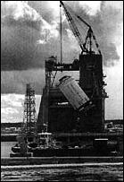
The most spectacular test-and test facilities-for the S-IC involved the static firing of the five F-I engines at full thrust. Two S-IC static test [207] stands were available, one at Huntsville and the other at the Mississippi Test Facility; both were similar in size and construction. The MTF facility was designed to include two test positions. Although MSFC conducted the first static tests of the S-IC in the summer of 1965, the MTF stand for the S-IC began operations about a year later and became the focus of the static test firing program. It seemed quite appropriate that the howling, thunderous roar of the S-IC cluster could so often be heard at an area originally known as Devil's Swamp.
At the time it was declared operational in 1966, the 124- meter-high test stand at MTF was the tallest building in the state of Mississippi. The concrete and steel tower rested on 1600 steel pilings, each 30 meters long, and the S-IC was secured by four huge hold-down arms anchored to a slab of concrete 12 meters thick. The massive jaws of the restraining arms clamped onto the rocket tail by means of drive mechanisms geared to move only 8 centimeters per minute. From a distance, the big test tower looked like a concrete monolith; its hollow legs were the equivalent of a 20-story building with offices, machine shops, data centers, and elevators. With the huge volume of LOX and kerosene in the rocket tanks, a catastrophic fire during testing was always a consideration; as a result all personnel were evacuated to remote bunkers before ignition. In case of a fire during a test, a water deluge system, evidenced by the myriad of pipes lacing up and down the structure, could spray 782 000 liters (215 000 gallons) per minute over the stand. Moreover, engine tests required a second water deluge system that supplied the stand with 1 100 000 liters (300 000 gallons) of water per minute through a double-walled steel flame bucket directly below the F-1 cluster. Thousands of holes in the outer walls of the flame bucket allowed water to gush out to cool the bucket and keep it intact for the next test. During a five-minute test run, the S-IC test stand got enough water to supply a city of 10 000 for a day.19
Any problems in the S-IC program seem to have occurred mostly at the start but were resolved before a serious impasse developed. Matt Urlaub recalled early confrontations between various Boeing and Marshall people over management issues. "Boeing...had a very strong sense of accomplishment up to that point, and they knew they had built large airplanes before, and this [S-IC] vehicle isn't much different... and we were, in those days, a pretty proud organization too." Both sides eventually adjusted, however, "getting the pecking order straight," as Urlaub put it. In 1963 the S-IC program encountered a succession of welding problems that persisted throughout the next year. Portions of the S-IC-T vehicle were scrapped because of welding deficiencies in the propellant tanks, and the S-IC-T generally lagged six weeks behind schedule during 1964. An upper LOX tank bulkhead for S-IC-S was scrapped "due to poor quality" in October, and at the same time, the manufacturing schedule for S-IC-T was reported to be 19 weeks behind....
 |
|
|
. |
|
|
. |
|
|
|
|
 |
.
|
| ||
|
. |
|
|
|
|
 |
|
| ||
[209] ....schedule because of a shortage in parts for the thrust structure. By November, Urlaub cautioned that the S-IC program was still behind schedule in several areas. The S-IC-1 flight stage, for instance, was lagging by three months. "Although the S-IC program may appear to be in the shadow of the S-II program," Urlaub said, "I think it would be unwise to pretend that now the entire Saturn program is paced by the upper stages."20
When the S-IC finally began its static firing tests in 1965, the chances for success of the Apollo-Saturn program brightened considerably. Early in 1966, the S-IVB stage was operational aboard the Saturn IB vehicle. The gloomiest clouds on the horizon in 1965-1966 were hovering over the North American plant on the West Coast, where the S-II second stage was still under development.
The vague outlines of the S-II took shape within the report of the Silverstein committee in December 1959, when its members recommended the development of the high-thrust, liquid- hydrogen-fueled engine. In less than a year, Rocketdyne won the contract for the J-2 engine. Because many of the engine design parameters depended on stage configuration and mission profiles, designers had also begun parallel design studies on the stage itself. These studies sprang from the Silverstein committee's original report, which included a LOX-LH2 propellant S-II stage (see chapter 2). Within weeks of the Silverstein committee's report, design and engine studies were in progress, and correlated, so that many features of the S-II design were under consideration more than 12 months before NASA began action for stage procurement.21
On the eve of his departure as Administrator, T. Keith Glennan wanted to make sure that an S-II stage received his successor's strongest attention. The only question was when to move. Glennan hedged a bit in January 1961, when Major General Don R. Ostrander, Director of the Office of Launch Vehicle Programs, pushed for definition of the C-2 vehicle configuration, including initiation of contract work for the S-II. Glennan hesitated because he did not want to "bind the new Administrator to an expenditure which will run several hundred millions of dollars," and because he felt it wiser to see how the J-2 engine program progressed. There was no doubt in his mind, however, concerning the desirability of the S-II stage as part of the C-2. The C-1 vehicle did not have the capabilities NASA needed for the long term. "The Saturn program is left in mid-stream," Glennan emphasized in the transition memo he left for his successor, "if the S-II stage is not developed and phased in as the second stage of the C-2 launch vehicle."22
Glennan's memo reflected the strong trend within NASA to move [210] toward a bigger vehicle with an LH2 stage, and not long after Webb's confirmation as the new Administrator in 1961, NASA authorized the Marshall center to proceed with contractor selection. MSFC's invitations to a preproposal conference in Huntsville in April attracted 30 aerospace firms. As described by MSFC at that time, the S-II second stage of the Saturn C-2 vehicle was presented as the largest rocket project, in terms of physical size, to be undertaken by American industry. Powered by four of the new J-2 engines, the preliminary configuration of the second stage was given dimensions of 22.5 meters in length and 6.5 meters in diameter. The implied challenge must have been sobering, since 23 of the companies did not submit proposals the following month for the first phase of the S-II contractor selection process. The seven firms left in the running included Aerojet General Corporation; Chrysler Corporation, Missile Division; Convair Astronautics Division of General Dynamics Corporation; Douglas Aircraft Corporation; Lockheed Aircraft Corporation, Georgia Division; Martin Company; and North American Aviation, Incorporated. They submitted briefs to MSFC concerning their experience and capability as potential contractors for the S-II stage.23
By June the contractors had been rated by a source evaluation board using a numerical scoring system geared to the phase one proposals. Three firms were eliminated, leaving Aerojet, Convair, Douglas, and North American. These four companies were about to receive a surprise, because NASA had decided to change the configuration of the second stage. On 8 June, Webb circulated a memo to his top advisors specifying that the Saturn C-2 simply could not boost the Apollo spacecraft to the escape velocity required for a circumlunar mission. NASA was now considering the C-3, which consisted of a fatter first stage powered by two F-1 engines and a larger S-II stage. As Webb noted, the C-3 had not yet been approved,24 and the four contractors, gathering late in June for the phase two conference, discovered they would have to grapple with some very loose ends.
The phase two conference opened with remarks by Oswald Lange, Chief of the Saturn Systems Office. In his initial statement, Lange explained why the C-2 configuration was going to be bypassed in favor of the C-3. Recent research on the problem of radiation in space indicated that the spacecraft needed more shielding, which would increase spacecraft weight from the original 6800-kilogram estimate to 13 600 kilograms. Moreover, Lange revealed, the original S-II diameter of 6.6 meters was now enlarged to 8.13 meters to be more compatible with the C-3's first stage and allow better payload flexibility in the future. On the other hand, Lange said, he was not able as yet to give the contractors hard figures on the exact configuration of the stages above the 8.13-meter S-II (making it difficult to figure out the mechanics of boost, separation of upper stages, and other aspects, as one contractor noted); indeed, MSFC might decide on an even larger 9.14-meter stage! "It may be a little hard [211] for you to speculate a design if we give you such soft indications of the configuration that we ultimately want," Lange admitted, but pledged to have firm numbers when Marshall and the winning contractor sat down to hammer out the details in final contract negotiations.
In a question-and-answer session that followed, a Marshall spokesman, after elaborating on some of the aspects of the proposals, apologetically echoed Lange, and explained that Marshall was anxious to get started on the contracts. "You can see that we have a whole lot of doubt in what we say here, and there are a lot of conflicting problems," the spokesman admitted. "We are presently trying to resolve them. We could have asked you not to come here today and could have taken, say, six weeks time to resolve these problems internally, in which case we would have lost six weeks on the S-II contract." Speaking with candor, he told the contractors, "This of course puts the monkey on your back, and we know that!" However, even with all of this looseness in the preliminary stages of finalizing the contract, Marshall made it clear that firm figures for the stage would be forthcoming, and that contractors would be held strictly accountable. As Wilbur Davis, of the MSFC Procurement and Contracts Office, stated it, "I wish to emphasize at this point that the important product that NASA will buy in this procurement is the efficient management of a stage system."25 Ironically, it was this very point that later contributed so much stress in relations between NASA and its chosen contractor.
North American won the prize; NASA announced the company's selection for the S-II contract on 11 September 1961.26 After consultation and search for a manufacturing site, a location at Seal Beach, California (not far from Long Beach), was chosen, and the facilities for constructing the S-II were built by the government. Coordination between North American, NASA, and the Navy, designated as the government's construction agency, did not always proceed well, and led to the dispatch of NASA investigation teams from Headquarters. In spite of the problems in the three-way arrangement, D. Brainerd Holmes emphasized in the spring of 1963 that "we are getting these facilities on time and the construction is excellent." By early autumn, North American was putting together the first S-II hardware components.27
The S-II turned out to be a comparatively advanced stage in terms of the existing state of the art. Although the S-II carried about 426 400 kilograms of liquid oxygen and liquid hydrogen, the tank structure, though supporting the structural mass, accounted for just a shade over three percent of the stage's total fueled weight. A common bulkhead much larger than that in any previous rocket averted the need for an [212] interstage between the oxidizer and fuel tanks; this reduced the total length of the stage by over 3 meters and saved about 4 metric tons of extra weight. In technical terms, the fabrication of the bulkheads called for unusually demanding accuracy in meridian welds that joined the bulkhead gores together. The welding operation joining the curved, 6-meter-long seams together had to be made to specifications allowing less than 0.33 millimeter of a mismatch. Then there was the problem of insulating the big liquid hydrogen tank, filled with thousands of liters of the super-cold propellant. Otherwise, the basic design elements of the S-II seemed conventional enough in that it consisted of eight major structural components and six major systems, all of which reflected the usual kind of basic elements associated with both the S-IC and the S-IVB.28
The vehicle was assembled at Seal Beach, where most of the major structural elements were fabricated. Exceptions were the interstage, aft skirt, thrust structure, and forward skirt which were produced at North American's plant in Tulsa, Oklahoma. The interstage, aft skirt, and forward skirt, all of semimonocoque construction, had been designed for structural rigidity. The thrust structure (in the usual inverted cone shape) featured both high-strength riveting and thrust longerons to handle the full thrust of the J-2 engine cluster. Fabricated in separate pieces, the aft skirt and thrust structure were intended to serve as a single structural entity when joined together. The combination served as a mounting point for the five engines, the heat shield, and assorted plumbing and black boxes.
In a sequence known as dual-plane separation, the interstage, although joined to the aft skirt, uncoupled from the S-II after staging from the S-IC. Following burnout of the first stage, a linear-shaped charge separated the S-II from the S-IC; this procedure was simultaneous with the firing of S-IC retrorockets and eight ullage motors on the interstage of the S-II. About 30 seconds after first-stage separation, the S-II interstage separated from the second stage itself. Initiation of the dual-plane separation maneuver occurred when the outboard J-2 engines reached 90 percent of their maximum thrust; at this point, explosive charges were triggered, which severed the interstage. The maneuver required a precise separation that would propel the interstage (5.4 meters long) rearward, clearing the engines by approximately 1 meter, while the S-II was accelerating to its blinding top speed. Once free of the interstage mass, the performance of the S-II was greatly enhanced. The dual-plane separation was an alternative to a method called "fire in the hole," which involved ignition and separation of the S-II while still contact with the interstage but not attached to it. Designers preferred to avoid this alternative because of possible perturbations and oscillations the end of the first-stage boost phase. With the S-II accelerating on an even course, it was easier to drop the interstage during that phase, rather [213] than risk hitting a wobbling interstage attached to the S-IC as the S-II pulled out.
The LOX tank of the S-II stage, like that of the S-IVB, incorporated the principle of the common bulkhead, which comprised the top half of the LOX tank. With its 10-meter diameter and 6.7-meter height, the ellipsoidal container had a squat appearance. Having no vertical walls to speak of, the LOX tank was constructed by welding together a dozen gores and finishing off the tank with "dollar sections," large circular pieces joining the ends of the gores at the top and bottom. The top of the LOX tank actually formed one half of the common bulkhead. After welding this part of the LOX tank, the common bulkhead was completed before adding the tank's bottom half to it. Early on, the forming of the gore segments for all the bulkhead assemblies frustrated manufacturing engineers, because no techniques existed for forming such large, unwieldy pieces. Each gore was approximately 2.6 meters wide at the base and had complex curvatures that were difficult to form accurately. After rejecting numerous possible procedures, the manufacturing team finally chose a somewhat exotic method-underwater explosive forming. This technique quite literally blasted the wedge-shaped gores into shape. North American's Los Angeles Division produced the gores, using a 211 000-liter (58 000-gallon) tank of water at nearby El Toro Marine Base for explosive, or "high-energy," forming. After positioning the gore segment in the tank, engineers detonated a carefully located network of primacord explosive, forming the metal by the blast transmitted through the water. The formation of each gore required three separate blasts.29
At the start of the S-II program, MSFC questioned North American's proposals for a common bulkhead. Despite the S-IV stage common bulkhead, engineers at Huntsville remained skeptical of North American's ability to produce a common bulkhead of the S-II diameter that would also withstand the additional stresses and pressures of much greater volumes of cryogenic propellants. Marshall insisted on parallel backup schemes using more conventional bulkhead designs, in case North American's idea failed. On the other hand, North American insisted on its common bulkhead to reduce stage length and weight from the conventional form of two separate fuel and oxidizer tanks connected by an interstage component. The company had to work out several new fabrication techniques to do the job.30
Beginning with the upper half of the LOX tank, fabrication of the common bulkhead required a number of carefully timed and sequenced operations. First, honeycomb phenolic insulation was fitted over the upper surface of the LOX tank dome, called the aft facing sheet because it served as the bottom of the common bulkhead. Then the insulation was bonded to the aft facing sheet and cured in a gargantuan autoclave. Next came the preliminary fitting of the forward facing sheet; this piece became the bottom half of the LH2 tank (also formed from large [214] wedge-shaped gores). Preliminary fitting of the forward facing sheet revealed surfaces in the insulation that needed to be filled in or shaved down for a perfect fit, using a machine controlled by data-tapes. Throughout the process, numerous checks were made to ensure that no gaps were left between the insulation and the facing sheets; ultrasonic equipment verified complete bonding of the adhesives.
Fitting the honeycomb core to the bulkhead domes was one of the most critical operations in the S-II manufacturing sequence. The chemically milled gores tapered from about 13 millimeters thickness at the base to 0.79 millimeter at the apex. With these thin sections, the great domes possessed relatively little strength by themselves and tended to sag; this situation created severe production problems in achieving the close fit required between the top and bottom domes and the insulation core. The honeycomb sandwich, which comprised the core, measured nearly 13 centimeters thick at the peak of the common bulkhead and tapered off at the bottom periphery, where more thickness was not necessary. So the honeycomb core, like the gores, had to be shaped to complex curvatures, tapered, and affixed without gaps to the flexible dome surfaces.
The procedure finally worked out by North American manufacturing teams was heralded by the company as "a major advance in missile fabrication." Workers applied a low pressure inflation force to the aft facing sheet, giving it full contour and providing accurate dimensional traces for fitting the honeycomb insulation core. The forward facing sheet presented a different problem; since the top surface of the insulation core had to be fitted to the underside of the forward facing sheet, the inflation technique was ruled out. Instead, NAA devised a huge vacuum bell. Fitted over the forward facing sheet, the vacuum bell sucked up the sheet to a fully contoured position. Afterward, handling slings lowered the entire assembly over the rigidly pressurized aft facing sheet to record the final set of dimensional traces for shaping the insulation surfaces.31
At the bottom edge of the forward facing sheet, a "J" shaped periphery provided the surface for welding it to the bottom cylinder wall of the LH2 tank. These "J-section" segments had to be separately machined and form-fitted. A circular weld at the "J-section," joining the LOX and LH2 tanks, was buttressed by a bolting ring; 636 high-strength bolts secured the bolting ring to flanges on the bottom LH2 tank cylinder and to the aft skirt section. The bottom cylinder measured only 69 centimeters high; the remaining five cylinder walls, each 2.4 meters high, were fabricated in four sections and welded together. The curved aluminum skins were machine-milled to leave stringers and ring frames for both structural rigidity and for mounting the internal slosh baffles. The LH2 forward bulkhead was fabricated of 12 gores, in much the same way as the LOX tank lower bulkhead.
Insulation for the LH2 tank created some of the most persistent [215] technical problems in the entire S-II program. North American chose external insulation, primarily for added material strength from the cryogenic effects of LH2 inside the fuel tank. This trade-off confronted the company with the problem of adequate external insulation and with special difficulties in bonding the insulation to the super-cold surfaces of the fuel tank. The original solution specified external insulation made of phenolic honeycomb filled with a heat-resistant foam of isocyanate. Fabricated in panels, the insulation material was sealed at the top and bottom with a phenolic laminate followed by a layer of Tedlar plastic film. The process of bonding the insulation panels to the tank created potential hazards. Air pockets next to the super-cold metal could be turned into puddles of liquid oxygen; these puddles could eventually weaken the bonding, thereby allowing large panels to peel off. To avoid this, the S-II stage featured a liquid-helium purge of the insulation through grooves cut into the insulation surface next to the tank walls. Helium flowed through the grooves from the start of hydrogen loading through countdown and up to the instant of launch.
Unfortunately, this design never worked very well. The purge system was tricky, the insulation bonding repeatedly failed, and chunks of insulation continued to fall off during tanking and test sequences. Although several S-II stages were produced with the original insulation concept, the results were so discouraging that North American spent considerable time and money working up an alternative. Instead of making up panels and affixing them to the tank, the company finally evolved a process for spraying insulation material directly onto the tank walls (eliminating the air pockets), letting it cure, then cutting it to the proper contour. This technique turned out to be much more economical and much lighter than the insulation panels.32
Eventually, all the parts of the S-II came together in the vertical assembly building at Seal Beach. Vertical assembly was chosen for its advantages in joining major parts and ease of welding. In vertical assembly, as opposed to horizontal assembly, it was easier to maintain circumference of the large diameter parts to close tolerances and gravitational force helped maintain stage alignment. Moreover, if the various cylinders and bulkheads were horizontal, temperature diversion about the circumference of the parts would produce distortions at the top of the piece being welded. Throughout each welding sequence, technicians employed a variety of special scopes, levels, and traditional plumb bobs to make sure alignments were exact. Additionally, the stage was subjected to hydrostatic, x-ray, dye penetrant, and other checks to ensure proper specifications. One of the last items to be added was the systems tunnel, affixed to the exterior of the stage. The tunnel, a semicircular structure, ran vertically up the side of the S-II and carried miscellaneous instrumentation along with wires and tubes that connected system components at the top and bottom of the stage.
[216] Final work inside the tanks included installation of slosh baffles, probes, and other miscellaneous equipment. In preparation for these operations, all surfaces inside the tanks were thoroughly cleansed, flushed with trichloroethylene, and dried. Flushing equipment consisted of a spray nozzle fitted to a movable lifting cylinder, similar to the hydraulic lifts used in filling stations. After the flushing, a team of technicians mounted a ladder and platform attachment on the movable lifting cylinder, entered the tanks, and began final installation of equipment. With all accessories installed, the tanks had to be flushed once again and the access ports sealed.
Finally, the engines were mounted, again using accurate aligning equipment to position each J-2 in the thrust frame attach points. Additional stage tests and systems checks preceded final preparation for shipping to the Mississippi Test Facility for the static-firing checks. After that-delivery to Cape Kennedy for launch.33
Of the six major systems, the propellant system was the most complex. The seven propellant subsystems included plumbing, hardware, and control to accomplish the following: purge, fill and replenish, venting, pressurization, propellant feed, recirculation, and propellant management. Elements were largely designed to cope with the tricky characteristics of the cryogenics carried on board the S-II stage. By using helium gas, the purge subsystem cleared the tank of contaminants like moisture (which could freeze and block valves or vents) in the LOX tank, and oxygen (which could freeze and create danger of explosions) in the LH2 tank. The fill and replenish subsystem (along with the recirculation cycle), helped relieve the tanks, valves, pumps, and feed lines of the thermal shocks encountered from the sudden introduction of ultra-cold propellants into the stage.
The recirculation subsystem kept propellants moving through the engine pumps and associated plumbing while keeping them properly chilled and ready for operation. Similarly, the fill and replenish system brought the propellant tanks and their related plumbing down to a temperature suitable for loading of the cryogenic propellants. The procedure began by circulating cold gas through the tanks and lines, followed by a "chilldown" cycle-slow pumping of propellants into the tanks until they reached the five percent level. Even with the preliminary cooling by chilled gas, the tanks were so much warmer than the propellants that much of the liquid boiled off when it first gushed into the tank; the "chilldown" dropped the tank temperatures to a point where fast fill could then proceed. Because the propellants were pumped into the tanks hours before liftoff and a certain amount of boil-off [217] persisted, constant replenishment was required until a minute or two before liftoff. Venting subsystems prevented overpressurization of the tanks, while a pressurization subsystem maintained propellant flow. Other subsystems for feeding the propellant from tanks to engines as well as propellant management (simultaneous depletion of tanks, engine cutoff, etc.) completed the propellant system network.
Other major systems (electrical, ordnance, measurement, thermal control, and flight control) were similar in basic functions to those on other Saturn stages. The same was true for the ground support operations for checkout, leak detection, engine compartment conditioning, and other equipment.34
The size of the S-Il included dimensions normally associated with the bulky fittings and burly strength of heavy industry. The inside of the S-II was roomy enough to stack three standard railroad tank cars end to end, with room to spare for a caboose lying sideways on top. Yet, the 24.8-meter stage weighed only 43 100 kilograms in its dry stage (by comparison, the three empty tank cars would weigh more than 95 700 kilograms). In spite of its massive appearance, the S-II was honed to the precise standards of the watchmaker. Almost one kilometer of welded joints had to be surgically clean and flawless, and many had to be accurate to 0.33 of a millimeter. The structural efficiency of the stage, in terms of the weight and pressures taken by its extra-thin walls, was comparable only to the capacity of one of nature's most refined examples of structural efficiency, the egg.
Even with all this description of the meticulous workmanship lavished on the S-II, the layman still might enquire, "so what?" What was so challenging, to the platoons of engineers and technicians who did it, about welding together a big rocket stage? One problem was the nature of the tank skins themselves. The S-II was built of an aluminum alloy known as 2014 T6, which was not generally favored for welding. North American knew the welding job was going to be complicated but wanted to use the alloy because of its enhanced strength under cryogenic conditions. A theme of the entire Saturn program was "size," and the challenges inherent in the S-II were similarly challenges of magnitude. With a diameter of 10 meters, the stage required circumferential welds of 31.4 meters. The longer the weld, the tougher the problem of sustaining quality and close tolerances-and in the S-II, weld quality and close tolerances were essential. A high quality weld pass of 1 meter might be one thing, but a virtually flawless circumferential weld of 31.4 meters promised all manner of increasing heat input problems and attendant [218] distortion problems where none could be tolerated. "I had very little gray hair when we started," admitted Norm Wilson, manager of the Manufacturing Engineering Section for the S-II at Seal Beach. "But look at me now," he said in 1968.35
Wilson's gray hair owed much to the multitude of variations and requirements implicit in the plethora of tricky welding tasks all over the stage, aside from the circumferential jobs. The various aluminum sheets joined together in the welding process varied in shape, size, and thickness, all of which caused different problems for the welder. One such joint had skins that tapered from 16 millimeters thick down to under 6 millimeters, then back up to 13 millimeters. The shifting thicknesses frequently made temperamental men of normally even-tempered welding engineers; weld speeds, arc voltages, and other regimes had to be tailored for each variance during the welding pass. Minuscule cracks, tiny bits of foreign material in the weld seams, moisture, or other apparently innocuous imperfections could leak volatile propellants or cause catastrophic weaknesses under the pressures and loads experienced in flight.
"You can't really say our work has been exotic," Wilson said. "But when you consider the sizes, angles, lengths, designs, offset tolerances, and overall specifications involved, you have one challenging welding problem on your hands. We've had to tap our experience well dry and tax our imagination to come up with the right answers, and it has been only through the combined contributions of many that we have been successful."36 It was a genuine team effort, with increasing reliance on automated welding technology. The virtuoso performances of the individual welder, plying his torch with sparks flying around his visored head, became an anachronism. In the case of the big bulkhead domes, the gore sections were joined two at a time while held rigidly by vacuum chucks in a precision-contoured welding jig. The welding torch, part of an automatic power pack, moved along an apparatus called a skate track, which was mounted on the exterior surface of the gores. Inching upward at a carefully geared speed, the automatic power pack "remembered" each detail of the three-step welding operation: trimming, welding, and x-raying in sequence. Each program for the automatic power pack evolved from elaborate trials on test panels; checking and rechecking the accuracy of the trim procedure; precise current, arc voltage, and welding speed for the torch head; and quality of the x-ray. A technician rode along on the track to monitor the procedure or stop it if necessary, but the machine basically did its own thing in its own way.
The tank cylinder walls posed a far different set of problems. Each wall was machined, formed, and assembled by many different manufacturing methods; each varied because of the stresses of movement from one industrial site to another, and exposure to different influences of heat and climate. One of the most difficult aspects originated in the initial [219] fabrication process. Each of the four cylinder sections was machined as a flat piece, then contoured to shape and welded together, with different stress factors from one completed cylinder to another. Before each welding operation, technicians reminded themselves that the cylinders were seldom true circles with nice flat surfaces for welding. During one of the first attempts to weld two cylinders together, 80 percent of the job was complete when the remaining section suddenly ballooned out of shape-the result of heat buildup and increasing stress from distortion. Exasperated specialists brainstormed the aggravating phenomenon, and tried to come up with a suitable "fix" for the problem. As a result, all the weld parameters had to be revised to include different tooling and new procedures using a series of "tack welds" evenly spaced around the circumference followed by three more passes using two skate welders operating simultaneously 180 degrees apart.
One of the most trying welding jobs in the whole operation was the joining of the forward LH2 bulkhead to the uppermost LH2 tank cylinder where the mismatch could be no more than 0.69 millimeter. Time after time, weld defects or mismatches occurred. Each reject required time-consuming efforts to cut open the weld, realign the pieces, and start over again. Delays at this step began to disrupt the whole program and raised the specter of late deliveries and slips in the launch schedule.
Late in 1966, a combined trouble-shooting committee was set up and jointly chaired by Werner Kuers, of the Manufacturing Engineering Laboratory at MSFC, and Ralph Ruud, executive vice-president of North American's Space & Information Systems Division. This joint approach to solving severe production problems was reflected down through the ranks, with contractor and NASA technicians working shoulder to shoulder in searching for answers. Among other things, the existing humidity conditions in the manufacturing area were reduced from 50-60 percent to only 30 percent to enhance the probability of better weld quality. An environmentally controlled, clean-room atmosphere was established by hanging huge canvas curtains in one corner of the assembly building. Personnel had to pass through a double-door airlock to get in and out of the welding area; they were required to wear white, lint-free smocks and gloves as well as step through an electric shoe brush machine to remove dirt picked up from the floor outside. Inside the clean-room area, workers continually mopped the epoxy floors to keep them free of moisture and extraneous particles; no smoking or eating was permitted in the area, and adjacent walls were painted a stark white to remind everyone in the vicinity to "think clean."
The Kuers-Ruud team recommended a major change in the welding procedure itself. North American welding engineers had been using their own "skate" system with the welding tool moving around the periphery of the stage. The new "rotary" method, based on prior MSFC experiments and previous applications in production of the S-IC stage, .....
![The S-ll stage of the Saturn V is shown in the cutaway drawing. [link to a larger picture]](p220as.jpg) |
|
 | ||
|
. |
|
|
|
|
 |
|
|
|
 |
|
. |
|
| ||
 |
.
|
.
| ||
|
. |
|
|
| |
 |
|
|
 | |
[222] ....consisted of the welding tool remaining stationary while the bulkhead and tank cylinder turned on a large, motorized table. Advantages accrued from the enhanced stability of the trim and weld head, better overall control of the process, and ease of operation because bulky cables and miscellaneous equipment could be kept in one spot and not hauled around the work floor. New techniques for alignment with adjustable screws spaced every few centimeters along alignment jigs, permitted nearly perfect match of the bulkhead and tank cylinder.
With manufacturing specifications of these magnitudes, North American experienced many long months of frustration until processes were completely under control. Not until January 1968 did the Space and Information Systems Division (S&ID) succeed in performing an error-free weld for the bulkhead-to-cylinder joint- accomplished in the buildup of S-II-9. By that time, there were only a half dozen stages left to produce. The previous stages had gone out the factory door with histories of shortcomings and corporate frustrations of considerable scope. The technical complexities of the S-II help explain the rash of problems encountered during its manufacture and test and served to highlight the trauma of NAA and S&ID's management under fire from NASA and from MSFC.37
As the weight of the Apollo payloads relentlessly climbed during the early 1960s, NASA engineers redoubled efforts to lighten the stages. To get one more kilogram of payload, the laws of orbital mechanics required that 14 kilograms be cut from the S-IC; or four to five kilograms from the S-II; but only one from the S-IVB. The S-IVB stage was already in production when the weight problem became acute-it was too late to slice anything from that stage, where the advantage was greatest. Trying to scrape 14 kilograms out of the S-IC to save 1 kilogram of payload just was not feasible in terms of time and effort. That left the S-II. As the second stage became a more finely honed and thin-shelled vehicle, the balance between success or failure became more delicate. This was especially true when welding the large, thin tank skins of the S-II stage.38
Manufacturing challenges such as reducing stage weight and the unusually long welding runs were not the only situations that escalated the S-II's troubles. Another persistent problem, for example, centered on the insulation for the LH2 tank. MSFC technical monitors became increasingly concerned during the spring of 1964 and reported "considerable difficulty" in perfecting adequate LH2 tank insulation; the growing problem crept up unawares, so to speak, and was reported with a note of surprise at MSFC. "The S-II stage insulation concept for vehicles 501, 502, 503 and to a somewhat lesser extent for S-II [ground-test vehicles] has not been fully qualified as of this date," read a memorandum dated 2 [223] June 1964. The memo candidly added, "This fact was discovered by Marshall personnel and came as quite a shock to S&ID management and needless to say, MSFC." The memo noted a number of anomalies, chief of which was the debonding of the nylon outer layer from the honeycomb material underneath when exposed to a simulated flight environment. The insulation difficulties became symptomatic. More serious production troubles appeared starting in October 1964, when burst tests revealed welded cylinder specimens lower in weld strength than anticipated. Then, on 28 October 1964, the first completed aft bulkhead for the S-II-S ruptured during a hydrostatic proof test, although at a lower pressure than specifications dictated. The fault was traced to a previous repair weld, done by hand, along a recirculation system service plate. While welding of a replacement bulkhead proceeded, a design change eliminated the welded service plate, making it an integral part of the bulkhead gore.39
The continuing snags involving the S-II began to cause worry lines in the brows of managers at MSFC and Headquarters; in particular was the need to get the first S-II flight stage, S-II-1, out the door at Seal Beach, tested, and delivered to Cape Kennedy for the first Saturn V launch, AS-501, in 1967. Production troubles with the S-II ground-test stages by late 1964 and early 1965 threatened the S-II-1 so much that MSFC's director, Wernher von Braun, proposed a reworking of the whole S-II test program to make up some of the slippages. Major General Samuel C. Phillips, from his vantage point as Director of the Apollo Program in Washington, concurred and set in motion a series of shortcuts in the spring of 1965 to put the S-II schedule back in shape. Specifically, NASA decided to cancel the dynamic test stage (S-II-D) and, instead, use the S-II-S for this purpose after its structural tests. This decision greatly relieved both manufacturing and assembly pressures on flight stages at Seal Beach and permitted use of S-II-D hardware in follow-on stages. Further, the "all-systems" test stage bypassed its scheduled tests at Santa Susana and was scheduled for direct delivery to MTF. Meanwhile, the S-II-F facility checkout stage was scheduled to bypass MTF (where the all-systems stage would be used for facility activation purposes) for delivery direct to the Cape. There, the S-II-F would be pressed immediately into service to give Launch Complex 39 a thorough and complete checkout before the first flight stage arrived. In addition to relieving pressure on the schedule, these changes netted a savings of $17 million.40
Following these early deviations, the S-II program appeared to be proceeding well until MSFC decided in May to freeze the configuration of the S-II. Explaining the decision, Arthur Rudolph, Saturn V Program Manager, said that because production hardware was in the process of fabrication, engineering change activities on vehicles and ground support equipment should be frozen to the "present baseline configuration." [224] Henceforth, only "absolutely mandatory" changes would be tolerated.41 During the spring and summer, there was reason to be encouraged by the progress on the S-II: successful battleship tests at Santa Susanna Field Laboratory, and accelerating work on the electromechanical mockup (the progress in the latter case owed a great deal to the addition of a third work shift, with each shift putting in six days a week).
Welding continued to be troublesome. Early in July, the Space and Information Systems Division (S&ID) began preparations for making the first circumferential welds on the S-II-1 (destined to be the first flight-rated stage). After completing the operation on 19 July, the weld was found to be faulty and repairs stretched into the first week of August before additional work on the S-II-1 could be started.42
Then the first incident in a chain of misfortunes occurred that created one of the most serious times of trouble in the development of the Saturn V. On 29 September 1965, the S-II-S/D (structures-dynamic-test stage) ruptured and fell apart during a loading test at Seal Beach. Destruction of the stage transpired during a test to simulate the forces acting on the stage at the end of the S-IC boost phase. MSFC quickly organized an ad hoc group to determine the reasons for the accident, tagging it with a rather dramatic title, the S-II-S/D Catastrophic Failure Evaluation Team. Additionally, Marshall added a Debris Evaluation Team to help pinpoint the component that caused the failure. While the Catastrophic Failure Evaluation Team started sifting reports, Colonel Sam Yarchin, the S-II Stage Manager, instructed the people at Seal Beach to untangle the twisted metal debris in the test tower and lay it out in orderly fashion inside a guarded enclosure for minute examination by the debris evaluation team. It was eventually determined that the point of failure had been in the aft skirt area at 144 percent of the limit load. Even though considerable data had been accumulated on this particular test and earlier tests, the loss of the stage left a void in the planned vehicle dynamic tests at Huntsville; the test program was juggled around to use the S-II-T stage instead, following static testing at MTF.43
The loss of S-II-S and continuing difficulties with the S-II at Seal Beach caused increasing consternation at MSFC. When the president of North American, J.L. Atwood, visited von Braun in Huntsville on 14 October, he found an indignant mood prevailing at Marshall. Brigadier General Edmund F.L. O'Connor, Director of MSFC's Industrial Operations, provided von Braun with some background data that included the following judgment: "The S-II program is out of control....It is apparent that management of the project at both the program level and division level at S&ID has not been effective.... In addition to the management problems, there are still significant technical difficulties in the S-II stage...."44 Obviously concerned, von Braun extracted promises from Atwood to put both a new man in charge of the S-II program and a [225] senior executive in a special position to monitor the plethora of technical delays and manufacturing problems.45
In an October letter to Harrison Storms, the president of S&ID, General O'Connor started with a friendly salutation ("Dear Stormy") and ended with assurances that MSFC wanted to help wherever possible to get the S-II program back on track. In between, the general minced no words. He pointed out that the breakdown in the S-II program reflected poorly on both S&ID and MSFC's management ability. O'Connor pointed a stern finger at S&ID, remarking that he was "most apprehensive" about the entire S-II program. "The continued inability or failure of S&ID to project with any reasonable accuracy their resource requirements, their inability to identify in a timely manner impending problems, and their inability to assess and relate resource requirements and problem areas to schedule impact, can lead me to only one conclusion," O'Connor declared, "that S&ID management does not have control of the Saturn S-II program."46 The chief of Marshall's industrial operations also conveyed his worry about the troublesome stage to the upper echelons of NASA management. Reviewing the problems during the annual program review at Headquarters in November, O'Connor noted managerial and technical shortcomings at North American and said that MSFC had "caused changes to be made in management; some people have been moved." In spite of help from the R&D operations laboratories at MSFC, problems in welding, inspection, insulation, and component qualification still existed, and as a result, the first S-II flight stage was more than three months behind schedule. "It is my opinion that program management at North American is perhaps the principal shortcoming of the entire S-II program," O'Connor said.47
The upshot of this administrative turbulence was the dispatch of a special "Tiger Team," headed by General Phillips, from the Apollo Program Office to North American. The Tiger Team appellation apparently came out of Phillips's Air Force experience-a special, ad hoc investigative group dispatched to dig into a problem area and come up with specific recommendations to solve the issues. As a later Associate Administrator for Manned Space Flight, Dale Myers, commented, "There is a need to terrorize the contractor once in a while." The result of that visit to North American was the soon-to-be famous Phillips report, which ripped into the company's management, not only on the S-II matter, but on the spacecraft as well.48
The impetus for this penetration of North American was a byproduct of a meeting of the President's Scientific Advisory Committee (PSAC), which convened at the Manned Spacecraft Center in Houston on 15 0ctober. Since a covey of high-level NASA executives was attending, Phillips took advantage of the situation by assembling a select group for an intense one-hour session following the PSAC sessions. The participants [226] included George Mueller, George Loss, and Joe Shea from Headquarters, along with Eberhard Rees from MSFC. The issue was North American's performance on the S-II. Rees briefed the group on plans to send "a group of selected experts from MSFC" to check on S&ID's operation on the S-II. The Marshall group, scheduled to leave on 18 October, was headed by Colonel Sam Yarchin, the program manager at Huntsville. Phillips wanted more than that. Rees reported that aside from MSFC's own S-II sleuths, Phillips wanted to take a close look at the entire S&ID operation "after Yarchin's committee has done some spade work." Phillips advocated a special survey team composed of top management from both MSC and MSFC; it was agreed to consider the matter in detail when von Braun visited Washington a few days later.49
On 27 October, Associate Administrator Mueller wrote to Lee Atwood advising him of what was coming. Mueller noted their mutual concern that the Apollo program should stay on course to a successful conclusion, but stressed severe problems in the rate of progress for both the S-II stage and the command and service modules (CSM). The purpose of the Phillips visit was to identify "those actions that either or both of us should take." General Phillips took Joe Shea from NASA Headquarters and Rees and O'Connor from MSFC. The group went to North American on 22 November and their report was due before Christmas.50
The "Phillips report," as it became known, was dispatched to Atwood over Phillips's signature on 19 December 1965. Briefly, Phillips told Atwood, "I am definitely not satisfied with the progress and outlook of either program.... The conclusions expressed in our briefing and xnotes are critical." The overall report was a thorough analysis of S&ID operations with various sub-teams investigating management, contracting, engineering. manufacturing, and reliability-quality control. Including Yarchin's "spadework" on the S-II, completed in early November, the thick document represented an almost unrelieved series of pointed criticisms of S&ID. Phillips offered one small ray of hope: "the right actions now can result in substantial improvement of position in both programs in the relatively near future."51 At this crucial juncture, Arthur Rudolph, head of MSFC's Saturn V Program Office, concluded that the S-II should not be starved for funds in the midst of its vicissitudes, and began massive infusions of dollars into the S-II project for overtime, increased manpower, R&D, and whatever else was necessary to see the job through.52
Eberhard Rees was prepared to invoke draconian measures unless the situation at North American showed distinct improvement. On 8 December 1965, he had composed a 13-page memorandum, "Personal Impressions, View and Recommendations," based on his S&ID reviews from 22 November through 4 December. The operation was far too big and bulky, Rees observed, making it unwieldy. It needed to be slimmed [227] down, and there needed to be much more awareness of progress and problems at the corporate level, which seemed to be dangerously insulated from its various divisions-S&ID in particular. In general, Rees seemed to view the situation with greater alarm than most. "It is not entirely impossible," he wrote, "that the first manned lunar landing may slip out of this decade considering, for instance, the present status of the S-II program" (emphasis in original copy).53
Rees obviously had further thoughts on this dire possibility, for on the next day he prepared an additional seven- page memorandum and attached it to the first. Marked "Sensitive, very limited MSF and MSFC Distribution," the memo was restricted to only three copies: the original to von Braun; one copy to Phillips; one copy for Rees's personal files. There were only a few encouraging signs at Seal Beach, he observed, and he hoped no serious dislocations would occur. Then, in a chillingly prophetic premonition, he wrote: "I do not want to elaborate on the possibility that we might lose the S-II-T stage by explosion and do heavy damage to the only test stand we have so far. But this possibility is not zero considering that Douglas blew up the S-IV-T on their stand with a more experienced crew and on a well broken in facility. Time delay in this case would be exorbitant."
One of the recurrent themes of the 9 December memo involved S&ID management. Rees expressed continuing uncertainty about the ability of Harrison Storms to cope with the snowballing costs and technical hangups of the S-II program. Robert E. Greer, a Storms aide, was the man to do the job in a crunch, Rees felt, and advocated Greer to take over direction of the S-II if necessary. MSFC should keep very close watch over S&ID, Rees advised, and if their performance did not improve in 1966, then, Rees added, "I believe NASA has to resort to very drastic measures." If the program still lagged, then NASA "should in all seriousness consider whether further S-II's should be contracted with NAA-S&ID." The bulk of S-II manufacturing facilities were owned by the government and could, if needed, be turned over to another contractor "in whom we have higher confidence." Rees admitted that serious dislocations would develop in the interim, but the possibility should be explored. "For me" be emphasized, "it is just unbearable to deal further with a non-performing contractor who has the government 'tightly over a barrel' when it comes to a multibillion dollar venture of such national importance as the Apollo Program." (emphasis in the original).54
With so much trauma surrounding North American's efforts in the S-II and CSM programs, a realignment of the company's managerial structure seemed inevitable. Already trying to get on the top of the S-II program in 1965, Storms named Robert E. Greer, a retired Air Force major general with a lean, Lincolnesque aura about him, as his special representative for the S-II. Greer had joined the company in July and took this assignment in October. By January 1966, in the wake of the [228] Phillips report, Greer became vice-president and program manager of the S-II program. In a somewhat unusual turn of events, the man Greer replaced, Bill Parker, stayed on as Greer's deputy. Parker had joined the company in 1948, serving as S-II program manager since 1961. The company's management obviously hoped that Parker's strong background in engineering and years of experience inside the company would complement Greer's managerial skills, recently honed as Assistant Chief of Staff for Guided Missiles at USAF Headquarters.55
In retrospect, Greer observed that the S-II program was indeed in bad shape. Among other things, he said that top management had poor visibility, and the lateral flow of information seemed to be weak. Greer updated and revitalized his management control center to enhance management's overall conception of progress (or lack of it) in the S-II program (see chapter 9 for details on management control centers). He also instituted more management meetings, carefully structured to help the lateral flow of information, as well as garner intelligence from a broader range of sources, vertically as well as laterally. The meetings were know at North American as "Black Saturdays." The term came from Greer's earlier experience in the Air Force Ballistic Missile Division, where the commanding officer, Brigadier General Bernard A. Schriever, convened such gatherings once a month. Those attending encompassed a broad spectrum of Schriever's command. When a program director raised an issue, Schriever wanted to be able to turn directly to a staffer or engineer for an answer or advice. When Greer took over the S-II program, he also had "Black Saturdays"-except that he had them every day, limited to 45 minutes each morning; later he cut their frequency to two or three times a week.
For attendees, Greer seemed to "over-invite" people, reaching rather far down the management ladder and including various technical personnel as well. A wide variety of problems were discussed, with planners and assembly-line engineers exchanging criticisms and recommendations. The experience spotlighted a lot of otherwise hard-to-see conflicts, and certainly improved overall visibility and awareness of the S-II's development. Greer made a point of personally visiting people at lower echelons of management and engineering to enhance employee morale and accumulate additional information for himself. In any case, Greer won the respect and admiration of many of his contemporaries at North American.56
Nevertheless, Greer's new administration took time to bring all the discordant xnotes of the S-II program into closer harmony. Growing restlessness spread through NASA Headquarters as the S-II-1 (the first flight stage) became the pacing item for AS-501. Early in 1966, George Mueller pointed out this dubious distinction to North American's president, but added a supportive note: "Your recent efforts to improve the [229] stage schedule position have been most gratifying and I am confident that there will be continuing improvement." As it turned out, the really difficult problem became the S-II-T, which, at the present, was undergoing testing at MTF. In April, one of Phillips's envoys at MTF reported serious problems in North American's personnel; the veteran group of test people sent to Mississippi on a temporary basis had gone back to California, leaving inexperienced personnel in charge. On 25 May 1966, one fire near some LH2 valves and another in the engine area curtailed a full-duration static test, although a successful full-duration (350 + seconds) test firing had been accomplished five days earlier. Atwood called von Braun to express his concern about the incident. Together, they discussed the probable cause, closing with discussion about different ways to expedite the program.
On 28 May 1966, a major blow to the Saturn V program came with the destruction of the S-II-T, the second S-II stage to be lost.57 Technicians had been trouble-shooting the causes of the fires that occurred during the static tests three days earlier. With the LH2 tank emptied, pressure checks, using helium were in progress. During prior tests, tank pressure sensors and relief switches had been disconnected, a fact unknown to the crew conducting the pressure checks, and as a result, the LH2 tank was pressurized beyond its design limits, ruptured, and was demolished. Five men from the North American test crew were injured, and two others were hospitalized for observation. The accident occurred on Saturday during the Memorial Day weekend. Von Braun had gone to a nearby lake for some rest and relaxation, and a distraught Harrison Storms, in trying to contact von Braun at home, could only reach von Braun's wife. Storms finally contacted von Braun on Tuesday, the day after Memorial Day. "I was at the lake," von Braun explained, "and she (my wife) told me that you were on the phone with a tear-choked voice." Von Braun was both sympathetic and stern. The loss of the S-II-T underscored the managerial weaknesses at MTF, he told Storms. With so many work shifts on and off the job, it was easy to foul things up. The contractor needed more seniority and better procedural control. The next day, in a call to Robert Gilruth at Houston, von Braun remarked that he saw nothing basically wrong in the design of the S-II. Its problems could be traced to management, procedure, and human error. The MSFC director summed up his view of the S-II's agonies in a terse assessment: "The whole thing is NAA, S&ID."58
Ripples of the S-II-T's destruction were felt in the launch schedule for AS-501; slippage in the S-II-1 flight stage had led to plans to use the S-II-T at Cape Kennedy to stack the AS-501 vehicle for systems tests and replace it later with the flight stage. Investigation of the S-II-T uncovered the presence of tiny cracks in the LH2 cylinders near the rupture area. Inspection of other manufactured stages and cylinders in production [230] revealed more minute cracks, leading to considerable delays in repair and modification work.59 Now, the successful launch of AS-501 depended even more heavily on successful testing of the first of the S-II-1 flight stages; the latter left Seal Beach on 31 July for a critical series of static firing and acceptance tests at MTF. By mid-August, the S-II was set up in Test Stand A-2 for checkout prior to static firing, which did not occur until the first of December. The intervening time was filled with a series of nettling problems-"the continuous surprises that keep occurring after the stages arrive on deck at MTF," as Rees complained to Storms during one of his weekly teleconferences.60 MSFC listed complaints on workmanship and quality control, including leaks around supposedly impervious seals; this situation led to the postponement of the first static test scheduled in late October.61
MSFC personnel found faults not only in the S-II-1 but in other stages. For example, the second flight stage, S-II-2, had been ordered back to the factory for numerous modifications and fixes. Many of the same operations had to be repeated on other components in various stages of fabrication and assembly. Managers at MSFC organized special Tiger Teams of technical and test operations personnel, dispatching them to MTF to assist in the static firing. All of this did little to cheer up the Apollo Program Office in Washington. During a year-end session of the annual program review, Phillips, still unhappy, summed up the assorted ills and tribulations of the S-II: "The performance of the contractor has not measured up to the minimum requirements of this program."62
With a few perturbations here and there, including a major change in the contractor's management, 1967 was a year of contrast for the S-II. During January, Phillips reported to the Office of Manned Space Flight (OMSF) that organization and test procedures had improved at MTF.63 To cope with the continuing problems at Seal Beach, MSFC sent a new Tiger Team, under the leadership of Colonel Yarchin, the S-II project manager, to the West Coast. Yarchin and 15 well-known technicians left early in January. This created questions in the aerospace press and elsewhere, about the nature and extent of North American's vicissitudes. MSFC prepared a statement as a guideline for use in answering questions raised by reporters, emphasizing the basic soundness of the S-II design, while admitting the need for MSFC's technical assistance in welding and other procedures at Seal Beach. By the end of the month, Phillips reported to the Associate Administrator that MSFC welding techniques had been adopted on the S-II. During March, a welding team from S&ID traveled to Marshall to observe techniques for reducing the frequency of weld defects in the circumferential welds of the LH2 tank.64
Besides the S-II program, the beleaguered management at North American was trying to cope with production problems and schedule slippages involving the command module. Concern for the CM issue [231] caused the Phillips team, which descended on North American in 1965, to include more people from the Manned Spacecraft Center in Houston (who had NASA responsibility for the CM) than from MSFC.65 Then, tragically on 27 January 1967, a flash fire in the CM during prelaunch tests at the Cape claimed the lives of astronauts Virgil I. Grissom, Edward White, II, and Roger B. Chaffee. The fire exacerbated NASA's concerns about the management structure of S&ID. The aftermath of the fire brought reworking of the CM and prelaunch test procedures and modification of many schedules. The delays, however, aided the Saturn vehicle contractors.66 The fire also triggered further reorganization of North American, as the company continued to contend with the persistent criticism of its performance from NASA. In a series of moves announced early in May 1967, company president Atwood streamlined S&ID and drastically shuffled his management team. The "information systems," part of Space and Information Systems Division, was snipped off and spliced into the Autonetics Division at Anaheim, leaving Space Division to concentrate on the Apollo program. Harrison Storms, relieved as president of S&ID (at Downey), became a corporate vice- president, and was replaced by William "Bill" Bergen, who had only recently resigned as president of the Martin Company, an aerospace firm in Baltimore, Maryland. Bergen was given the assistance of some of North American's top executive experts. Paul Vogt, newly appointed vice-president in the Space Division, had special responsibility for improving engineering, manufacturing, and quality control. Ralph H. Ruud, an expert on materials and quality control and former corporate vice-president for manufacturing, took over as Bergen's executive vice- president. In addition, North American management at the Cape was realigned into a more unified structure reporting directly to Bastian "Buzz" Hello, who came with Bergen from the Martin Company.67
In the meantime, delivery of the S-II-1 stage to the Cape in late January prompted cautious optimism about the overall progress for the Saturn booster; this optimism was short-lived, clouded by mounting requirements for "open work" on the stage, involving modifications to hardware that only recently had emerged from production lines. "This growth in modifications downstream all the way to the stack at KSC must be arrested," Mueller told the president of North American. "We simply must attain early definition of the work to be accomplished at the proper station and ship complete stages to MTF and KSC."68 As an example of these vexatious problems, tiny "hairline" cracks found in S-II tankage under manufacture led to a huddle in Washington on the possibility of similar faults in the S-II-1 already stacked with other stages for the AS-501 launch. With the launch scheduled for mid-August, individuals meeting at NASA Headquarters on the afternoon of 24 May considered the possibility of missing the launch date because of the inspection work to be done on S-II-1. The top-level decision group, including Phillips, [232] von Braun, Debus, O'Connor, Rudolph, and Yarchin came to the only safe decision: take down the S-II-1 and conduct extensive dye penetrant and x-ray inspection of the welds in the LOX and LH2 tanks.69 The inspection uncovered a dozen imperfections requiring careful tank repairs and burnishing of the tank walls. The original August launch date kept slipping, but other modifications were also made to the rest of the vehicle and the ground equipment. It was not the sole fault of S-II-1 that AS-501 did not leave the pad until 9 November 1967.70
It would be inaccurate to say that the S-IC project waltzed through its development without a stumble. Still, there were decidedly fewer traumas with it than with the S-II. The S-IC clearly profited from the close association with MSFC's own fabrication and manufacturing specialists early in the game. The use of conventional propellants like RP-1 and liquid oxygen represented a lower magnitude of difficulty in producing tanks and accessories.
North American had trouble with the S-II, at least in part, because the company had some management difficulties. In fact, the problems, had been growing many months before the crisis of 1965-1966. Von Braun's "Daily Journal" expressed concern about management shortcomings as early as 1963, citing problems in cost overruns and organization of manufacturing units.71 Moreover, the S-II program got caught in a weight-shaving program, which made working with its extremely thin-walled tanks and other lightened hardware even more difficult.
The turn-around for the S-II by 1967 resulted from the resolute, though agonizing, reorganization of North American's management. The reorganization created better visibility and more direct interaction between corporate managers and the divisions, and benefited from the streamlining of S&ID itself, and the ability of Robert Greer. Greer's combination of managerial skills and the ability to come to terms with the technical problems commanded the respect, loyalty, and performance from North American's workers at a crucial time. North American was competent to do the job; reorganization and tighter management enabled North American's capabilities to be applied more effectively.72
Finally, the influence from NASA Headquarters and from MSFC was extremely significant. The thorough assessment by the Phillips team influenced North American's realignment in the right direction. Added to this was the impact of various technical teams from MSFC dispatch to Seal Beach and MTF to help solve perplexing hardware problems and operational snarls. Sometimes this was a hindrance. In Greer's opinion, Marshall's ubiquitous engineers and direction from Huntsville reach the point where North American's attempts to catch up were snarled by NASA's red tape.73
[233] In spite of all the early predicaments in the Saturn program caused by the S-II, the Saturn V nevertheless launched men to the moon within the decade; and the S-II stage, along with other Saturn components, compiled a perfect record of successful missions.
In part, the success of such complex machines rested on new plateaus of achievement in electronic circuitry and computer technology.
* North American
Aviation merged with Rockwell Standard in 1967, becoming North
American Rockwell (NAR), and later, Rockwell International. For
convenience, the term North American is used in the narrative.